Review Questions for Operating Testing and Preventative Maintenance of Electrical Power Aparatus
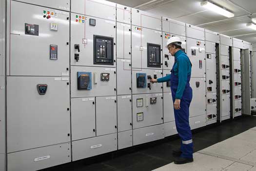
Switchgear maintenance is essential for continued reliable operation. Photo: Twins Chip Electrical Industry
Substations and switchgear in an electrical arrangement perform the functions of voltage transformation, system protection, ability factor correction metering, and circuit switching.
Electrical power aparatus, such as transformers, regulators, air switches, circuit breakers, capacitors, and lightning arresters contain the components necessary to perform these functions.
This guide provides a general overview for the inspection, testing and maintenance techniques used on switchgear and switchboard assemblies, and their associated components.
Safety Considerations
Alert: Only qualified electrical personnel familiar with the equipment, its operation and the associated hazards should be permitted to work on switchboards and switchgear. Always exist certain that the chief and secondary circuits are de-energized before attempting whatsoever testing or maintenance.
General Visual and Mechanical Inspection of Switchgear
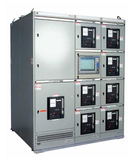
Switchgear should be inspected for proper anchorage, alignment, grounding and required clearances. Photo: General Electric.
1.) Audit the physical, electrical, and mechanical condition of switchgear or switchboard, including its anchorage, alignment, grounding and required clearances. When performing acceptance testing, verify that the equipment nameplate information matches project drawings and specifications. This is of import considering switchboards are designed and rated for specific applications and should not be used otherwise, unless explicitly canonical past the manufacturer.
2.) The unit of measurement should be make clean and all shipping braces, loose parts, and documentation shipped within the cubicles removed. Go on all documentation in a safety location for maintenance personnel in the future while loose parts and switchgear tools should be safely stored exterior of the enclosure for easy access. When performing maintenance programs, clean the assembly using electircal industry accepted methods of cleaning.
3.) For initial acceptance, verify that fuse and/or excursion billow sizes, types, and protective device settings match the projection drawings and coordination study. Excursion breaker'due south equipped with microprocessor-communication packages should be programmed with the proper digital address. All musical instrument transformer current and voltage ratios should as well represent to project drawings.
Moisture and Corona Inspections for Switchgear and Switchboards
If corona occurs in switchgear assemblies, information technology is usually localized in sparse air gaps that exist between a high-voltage bus bar and its adjacent insulation or between 2 next insulating members. Corona might also form around bolt heads or other sharp projections that are not properly insulated or shielded. Corona in depression-voltage switchgear is practically nonexistent.
1.) Inspect for evidence of moisture or corona when performing maintenance inspections. On outdoor assemblies, roof or wall seams should be checked for evidence of leakage, and whatever leaking seams should exist sealed with weatherproof caulk.
Prolonged leakage can exist identified by rust or water marks on surfaces side by side to and beneath leaky seams. The assembly base should be checked for openings that could let water to drain into the interior, and any such openings should be caulked or grouted. Larger openings should be sealed to forbid rodent intrusion.
Many electrical inspection protocols call for using ultrasound to test enclosed electrical gear before opening to forestall arc flash incidents. Video: UE Systems Europe.
two.) All interior and outside lighting should be checked for proper operation. It is essential for personnel condom that the area be well lit at all times in case of emergency response and other security reasons.
Wiring and Bolted Connexion Checks for Switchgear and Switchboards
one.) Bolted electrical connections should exist inspected for high resistance, either by apply of a low-resistance ohmmeter (DLRO), calibrated torque-wrench, or infrared scan. Loose bolted electric connections tin lead to college free energy consumption and eventual equipment failure if not properly addressed.
- When using a depression-resistance ohmmeter, investigate values which deviate from those of like bolted connections by more than fifty percent of the lowest value.
- Bolt-torque levels should be in accordance with manufacturer's published data. Utilise NETA Table 100.12 in the absenteeism of manufacturer's data.
General Wiring Checks for Switchgear and Switchboards
Loose command wires tin atomic number 82 to catastrophic failure if they are role of a critical protective excursion, such as a protective relay for a circuit breaker. Other critical functions like electrical charging and re-closing of circuit breakers tin be inhibited if poor connections overheat and lose integrity.
1.) Check that all wiring connections are tight and that wiring is secure to prevent damage during routine operation of moving parts, especially when removing draw-out excursion breakers or opening and closing cubicle doors. Gently tug on command wires to ensure a tight connection or use a screwdriver to gently verify torque on the connection. Infrared scans are too very constructive for finding loose wires in control circuits.
Moving Parts and Interlock Checks for Switchgear and Switchboards
ane.) Ostend the right performance and sequencing of electrical and mechanical interlock systems. Attempt closure on locked-open up devices and endeavor to open locked-airtight devices.
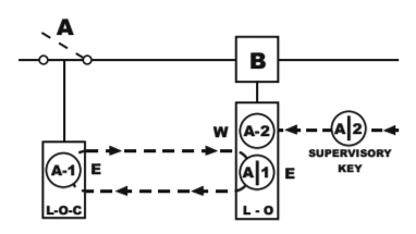
Fundamental Interlock Scheme Example. Photo: Kirk Key Interlocks
2.) Test primal interlock systems by making key exchanges with all devices included in the interlock scheme as applicable. All of these systems are essential for safety of both the operator and the equipment.
Lubrication of Switchgear and Switchboards
ane.) Check for advisable lubrication on moving electric current-carrying parts and moving/sliding surfaces to proceed everything operating smoothly. This includes hinges, locks, and latches when performing maintenance tests. Lubricate every bit necessary using manufacturer standard accepted lubrications and techniques.
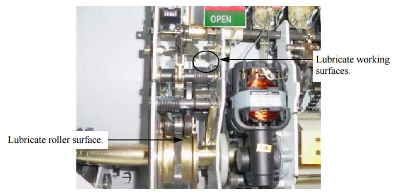
Inspect the lubrication state of the excursion breaker operating mechanism latch faces and rollers. Photo Credit: ABB
Insulators and Barrier Checks for Switchgear and Switchboards
Tracking is an electric belch phenomenon caused by electrical stress on insulation. This stress tin occur phase-to-phase or phase-to-basis. Although tracking tin occur internally in certain insulating materials, these materials as a rule are not used in medium- or loftier-voltage switchgear insulation. Tracking, when it occurs in switchgear assemblies, normally is found on insulation surfaces.
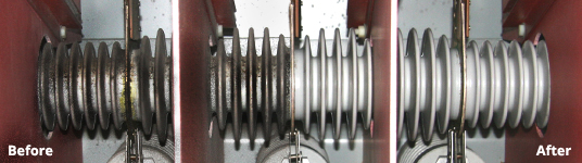
Accumulated dirt, oil or grease might require liquid solvents or other alternative methods to exist removed. Photograph Credit: Wickens Dry Ice Diggings
1.) Electrical insulators should be inspected for evidence of physical impairment or contaminated surfaces. Damage acquired by electrical distress is ordinarily evident on the surface of insulating members in the grade of corona erosion or markings or tracking paths.
2.) Inspect barrier and shutter assemblies for proper installation and operation. All active components should be exercised, mechanical indicating devices should exist inspected for correct operation.
Case of switchgear shutter functioning. Video by Twins Chip Electrical Industry.
three.) Ensure that vents are clear and filters are in place. Screens roofing ventilation openings should be in place to prevent entry of rodents or small animals.
Bolted Connection Electrical Tests for Switchgear and Switchboards
1.) Perform resistance measurements through bolted electric connections with a low-resistance ohmmeter. Measure line/load motorcoach resistance cease-to-end and to each distribution department.
two.) Verify dual-source switchgear bussing is correct at the tie breaker. Compare resistance values to values of similar connections and investigate values that deviate by more than fifty percent of the everyman value.
Case:
A-phase bus measures 109 microhms, B-stage motorcoach measures 90 microhms, C-stage jitney measures 135 microhms. Investigate values that deviate past more than l% of 90 microhms (90 * 1.5 = 135 microhms).
Insulation Electrical Tests for Switchgear and Switchboards
1.) Insulation�resistance tests should exist performed with a megohmmeter for one minute on each omnibus section, phase-to-phase and stage-to-ground. The exam voltage to exist used is dependent on the rating of the equipment and should be practical in accord with manufacturer's published information. ANSI/NETA Table 100.ane tin can be used as a guideline if manufacturer's data cannot be found.
2.) Insulation-resistance values of double-decker insulation depends on voltage class and should be in accord with manufacturer's published data or ANSI/NETA Tabular array 100.1. Values of insulation resistance less than Table 100.1 or manufacturer's recommendations should be investigated.
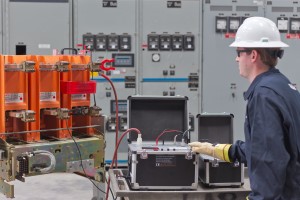
Dielectric Withstand Examination for Switchgear and Switchboards
ane.) Perform a dielectric withstand voltage examination on each double-decker section, each phase-to-ground with phases not under examination grounded, using a exam voltage in accordance with manufacturer's published data. If no manufacturer recommendation for this test exists, reference ANSI/NETA Table 100.ii.
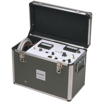
Photograph: Air conditioning Hipots are recommended for dielectric withstand testing circuit breakers. Photo: HV, Inc.
2.) Apply test voltage for ane minute. If no evidence of distress or insulation failure is observed by the end of the full time of voltage application, the exam specimen is considered to take passed the exam.
Of import: Dielectric withstand voltage tests should non proceed until insulation-resistance levels are raised above the recommended minimum values. Dielectric Withstand is an optional test when performing routine maintenance per ANSI/NETA-MTS 2019 Section vii.1.B.three.
Control Wiring Electrical Tests for Switchgear and Switchboards
i.) Perform insulation-resistance tests on control wiring with respect to footing. Apply 500 volts dc for 300-volt rated cable and 1000 volts dc for 600-volt rated cable for one infinitesimal each.
Important: Units with solid-state components could be damaged if not properly isolated (via removal of plugs and/or fuses) earlier applying test voltage. Be sure to follow all manufacturers' recommendations when performing dielectric tests on solid state components.
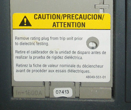
Solid-state components could be damaged if non properly isolated before applying test voltage. Photo: Square D.
two.) Minimum insulation-resistance values of control wiring should be comparable to previously obtained results only not less than ii megohms. This test is optional for both maintenance and initial acceptance. Refer to NETA-ATS/MTS Section 7.1.B.iv for more information.
Instrument Transformer Tests for Switchgear and Switchboards

Electric current transformers are only some of the many musical instrument transformers found in switchgear and switchboards. Photo: ABB.
The procedure for inspecting and testing instrument transformers is beyond the telescopic of this guide as each type has its own procedure. Instrument transformers generally include current transformers, voltage transformers, and control power transformers. Conduct electric tests on musical instrument transformers in accordance with ANSI/NETA Section 7.10. Where applicable, testing of instrument transformers generally include:
- Visual/Mechanical Inspection
- Insulation Resistance Test
- Dielectric Withstand
- Turns Ratio Tests
- Excitation Tests
- Burden Test
- Ability/Dissipation Gene
- Secondary Wiring Integrity
Results of electrical tests on instrument transformers should exist in accordance with ANSI/NETA Department seven.x.
Circuit Billow and Switch Tests for Switchgear and Switchboards
It'due south essential that circuit breakers be tested and maintained to ensure proper operation during electrical faults. Photo: Vacuum Interrupter Testing
The process for the inspection/testing of circuit breakers and switches is beyond the scope of this guide as each type and voltage class has its own procedure. Conduct electric tests on circuit breakers in accordance with ANSI/NETA Department seven. Where applicable, testing of circuit breakers more often than not include:
- Visual/Mechanical Inspection
- Insulation Resistance
- Dielectric Withstand
- Contact/Pole Resistance
- Electrical Operations
- Vacuum Integrity / Magnetron Atmospheric Status (MAC)
- Power/Dissipation Factor
- Protective Devices and Instrument Transformers
Results of electric tests on circuit breakers and switches should be in accordance with ANSI/NETA Section 7.
Control Power Transfer Scheme Examination for Switchgear and Switchboards
1.) Switchgear and switchboard assemblies equipped with multiple control power sources should be checked for proper function of the control transfer scheme by connecting a rated secondary voltage to each source. Transfer relays should perform as designed when the master source is lost.
Ground Resistance Electrical Tests for Switchgear and Switchboards
one.) Perform resistance measurements through bolted ground connections with a low-resistance ohmmeter, if applicable. Compare bolted connection resistance values to values of similar connections and investigate values which deviate from those of similar bolted connections by more than fifty percent of the lowest value.
2.) Determine the resistance betwixt the primary grounding arrangement and all major electrical equipment frames, system neutral, and derived neutral points by ways of signal-to-point testing using a low-resistance ohmmeter. Values which exceed 0.5 ohm should be investigated.
3.) Perform a autumn-of-potential or lternative basis resistance test in accordance with IEEE 81 on the main grounding electrode or organisation. The resistance between the main grounding electrode and ground should be no greater than five ohms for large commercial or industrial systems and ane ohm or less for generating or transmission station grounds, unless otherwise specified by the owner. Reference IEEE Standard 142 for more than information on this topic.
Metering Electrical Tests for Switchgear and Switchboards
Metering devices are verified using secondary voltage and electric current levels. Photo: EATON
Metering device inspections and tests are beyond the scope of this guide. Generally, metering devices are verified using secondary voltage and current levels supplied by a relay test set or other secondary source.
i.) Determine accuracy of all meters and calibrate watthour meters in accordance with ANSI/NETA Section 7.11.
Current Injection Tests for Switchgear and Switchboards
Current-injection tests will testify current wiring is in accordance with design specifications. This is an optional examination co-ordinate to ANSI/NETA.
1.) Perform current-injection tests on the entire current circuit in each section of switchgear by secondary injection with magnitudes that produce a minimum electric current of 1.0 ampere flows in the secondary circuit. Verify correct magnitude of electric current at each device in the circuit.
System Role Test for Switchgear and Switchboards
The process for Arrangement Functional Testing exceeds far beyond the telescopic of this document. Organization function tests should be performed in accordance with ANSI/NETA-ATS Section eight during initial switchgear/switchboard acceptance. Results of system role tests should be in accord with ANSI/NETA-ATS Section 8.
Cubicle Heater Tests for Switchgear and Switchboards
Moisture accumulation is prevented by rut and air circulation. Information technology'south important, therefore, to make certain the heating and ventilating systems are functioning properly to reduce internal condensation.
1.) The operation of switchgear/switchboard heaters should exist verified along with their controller. Heaters should be operational.
Tip: Infrared cameras are the easiest fashion to verify heater functionality without making contact with energized electrical equipment.
Surge Arrester Tests for Switchgear and Switchboards
Inspection and testing procedures for surge arresters exceeds the scope of this document. Surge Arresters should exist performed in accordance with ANSI/NETA-ATS Section seven.19. Testing these devices typically consist of applying a high voltage across the arrester to ground and observing the leakage current.
Recommended: Surge Arrester Field Maintenance and Testing
Dual-Source Phasing Check for Switchgear and Switchboards
1.) During initial credence, perform phasing checks on double-ended or dual-source switchgear to insure right omnibus phasing from each source. Phasing checks should testify the switchgear or switchboard phasing is right and in accordance with the system design.
Remember to always follow rubber work practices when performing energized work!
References
- ANSI/NETA Standard for Acceptance Testing Specifications 2013 Edition
- ANSI/NETA Standard for Maintenance Testing Specifications 2015 Edition
- NFPA-70B Recommended Practise for Electrical Equipment Maintenance
Comments
one total comments
Leave a annotate Login or Register to annotate.
Source: https://testguy.net/content/258-switchgear-and-switchboard-inspection-and-testing-guide
0 Response to "Review Questions for Operating Testing and Preventative Maintenance of Electrical Power Aparatus"
Post a Comment